


Box2D C++ tutorials - Joints - prismatic
Last edited: July 14 2013Chinese version -> 中文
Prismatic joints
The prismatic joint is probably more commonly known as a slider joint. The two joined bodies have their rotation held fixed relative to each other, and they can only move along a specified axis. Prismatic joints can be given limits so that the bodies can only move along the axis within a specific range. They can also be given a motor so that the bodies will try to move at a given speed, with a given force. Common uses for prismatic joints include:
- elevators
- moving platforms
- sliding doors
- pistons
Creating a prismatic joint
A prismatic joint is created by first setting the desired properties in a b2PrismaticJointDef, then passing that to CreateJoint to get an instance of a b2PrismaticJoint object. We saw in the joints overview that all joint definitions have some properties in common - the two bodies to be joined, and whether they should collide with each other. So we'll set those first:
1 2 3 4 | b2PrismaticJointDef prismaticJointDef; prismaticJointDef.bodyA = bodyA; prismaticJointDef.bodyB = bodyB; prismaticJointDef.collideConnected = false; |
- localAxis1* - the axis (line) of movement (relative to bodyA)
- referenceAngle - the angle to be enforced between the bodies
- localAnchorA - a point in body A to keep on the axis line
- localAnchorB - a point in body B to keep on the axis line
- enableLimit - whether the joint limits will be active
- lowerTranslation - position of the lower limit
- upperTranslation - position of the upper limit
- enableMotor - whether the joint motor will be active
- motorSpeed - the target speed of the joint motor
- maxMotorForce - the maximum allowable force the motor can use
Let's take a look at what these do in more detail.
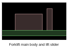
As an example of setting up prismatic joints, we'll make a simple forklift. This will make use of joint limits and motors. Here are the bodies we'll use for this - one large box for the chassis and a smaller one for the lift slider. Since we have already covered many examples I will no longer be showing the full listing for all the code, but it's probably convenient to start with a basic 'fenced in' type scene as in some of the previous topics to stop things flying off the screen.
1 2 3 4 5 6 7 8 9 10 11 12 13 14 15 16 17 18 19 20 21 22 23 | //body and fixture defs - the common parts b2BodyDef bodyDef; bodyDef.type = b2_dynamicBody; b2FixtureDef fixtureDef; fixtureDef.density = 1; //two boxes b2PolygonShape squareShapeA; squareShapeA.SetAsBox(5,3); b2PolygonShape squareShapeB; squareShapeB.SetAsBox(1,4); //large box a little to the left bodyDef.position.Set(-10, 10); fixtureDef.shape = &squareShapeA; m_bodyA = m_world->CreateBody( &bodyDef ); m_bodyA->CreateFixture( &fixtureDef ); //smaller box a little to the right bodyDef.position.Set( -4, 10); fixtureDef.shape = &squareShapeB; m_bodyB = m_world->CreateBody( &bodyDef ); m_bodyB->CreateFixture( &fixtureDef ); |
Joint axis
The joint axis is the line along which the bodies can move relative to each other. It is specified in bodyA's local coordinates, so you could think of it as the direction bodyB can move from bodyA's point of view. For example if bodyA has a trapezoidal fixture, and bodyB has a square polygon fixture as below, and you want bodyB to be able to slide along the direction the trapezoid is 'pointing'...
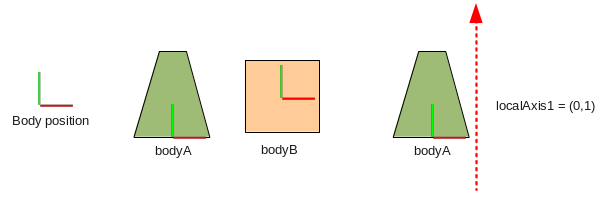 ...you would need a local axis of (0,1). So the code for this case
would be:
...you would need a local axis of (0,1). So the code for this case
would be:
1 | prismaticJointDef.localAxis1.Set(0,1); |
This means that as bodyA moves around in the world, the line along which bodyB can slide will move with it, for example:
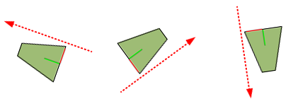 Note that the axis itself is not related to any particular point in the body, it only specifies
a direction for the sliding movement. That's why I have intentionally shown it outside the body's fixture
in the diagram :) The axis given should be a unit vector, so before you create
the joint remember to normalize the vector if it had a length other than 1:
Note that the axis itself is not related to any particular point in the body, it only specifies
a direction for the sliding movement. That's why I have intentionally shown it outside the body's fixture
in the diagram :) The axis given should be a unit vector, so before you create
the joint remember to normalize the vector if it had a length other than 1:
1 | prismaticJointDef.localAxis1.Normalize(); |
Let's make the axis for our forklift joint (0,1) so that a positive movement in the axis raises the lift slider.
Local anchors
Now that we have established the direction along which the two bodies should move with respect to each other, we can specify points on each body that should stay on the axis line. These are given in local coordinates for each body, so you need to remember to look from the point of view of the body in question. Getting back to the forklift example, let's say we want to have the lift slider (bodyB) a little to the right of the main body (bodyA). We could use positions like this:

1 2 | prismaticJointDef.localAnchorA.Set( 6,-3);//a little outside the bottom right corner prismaticJointDef.localAnchorB.Set(-1,-4);//bottom left corner |
1 | m_joint = (b2PrismaticJoint*)m_world->CreateJoint( &prismaticJointDef ); |
 Since the axis of the joint is (0,1) and none of the bodies are rotated, we could actually have used
any old value for the y-value of these anchor points and the bodies would still slide along the same
line. However, when we want to set limits for the joint we'll need to be aware of where these points
are on the line in order to get the limits in the right place. To make it easier to understand the
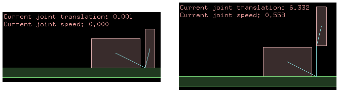
values for joint limits in the sections below, let's add some output on the screen to show the current
joint translation and speed:
Since the axis of the joint is (0,1) and none of the bodies are rotated, we could actually have used
any old value for the y-value of these anchor points and the bodies would still slide along the same
line. However, when we want to set limits for the joint we'll need to be aware of where these points
are on the line in order to get the limits in the right place. To make it easier to understand the
values for joint limits in the sections below, let's add some output on the screen to show the current
joint translation and speed:
1 2 3 4 5 | //in Step() m_debugDraw.DrawString(5, m_textLine, "Current joint translation: %.3f", m_joint->GetJointTranslation()); m_textLine += 15; m_debugDraw.DrawString(5, m_textLine, "Current joint speed: %.3f", m_joint->GetJointSpeed()); m_textLine += 15; |
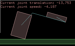
 If you pick the bodies up and move them around you'll see how the axis is always the same relative to the
two bodies, and the translation is only measured along this axis.
If you pick the bodies up and move them around you'll see how the axis is always the same relative to the
two bodies, and the translation is only measured along this axis.
Reference angle
The angles of the bodies in this example started at the default angle of zero, and when we constrain them with the prismatic joint they cannot rotate to any other angle (relative to the other body). If we want to have a different angle between the bodies, we can set that with the reference angle property of the prismatic joint definition. The reference angle is given as the angle of bodyB, as seen from bodyA's point of view.
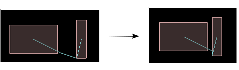
As an example, let's say we want the lift slider body to be tilted back a little to help keep the cargo from falling off the forks. We can give the joint a reference angle of 5 degrees, which will make the joint hold bodyB at 5 degrees counter-clockwise to bodyA.
1 | prismaticJointDef.referenceAngle = 5 * DEGTORAD; |
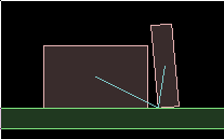 Note that since the local anchor point of each body is constrained to be on the axis line, the reference
angle effectively causes bodyB to rotate around the local anchor point (at the bottom left corner).
Note that since the local anchor point of each body is constrained to be on the axis line, the reference
angle effectively causes bodyB to rotate around the local anchor point (at the bottom left corner).Prismatic joint limits
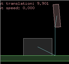
With the settings made so far the two bodies are free to slide along the line indefinitely, but we can limit this range of motion by specifying limits for the joint. Joint limits define a lower and upper bound on the joint translation within which the bodies will be kept. This is where it comes in handy to have the joint translation displayed on the screen, so we can easily see where the limits should be set by moving the bodies around a bit. For this forklift example, we could set the lower limit at zero (this is where the lift slider body touches the ground) and the upper limit at hmm... about 10 looks fine.
1 2 3 | prismaticJointDef.enableLimit = true; prismaticJointDef.lowerTranslation = 0; prismaticJointDef.upperTranslation = 10; |
 The default value for enableLimit is false. You can also get or set these limit properties for
a prismatic joint after it has been created, by using these functions:
The default value for enableLimit is false. You can also get or set these limit properties for
a prismatic joint after it has been created, by using these functions:
1 2 3 4 5 6 7 8 | //alter joint limits void EnableLimit(bool enabled); void SetLimits( float lower, float upper ); //query joint limits bool IsLimitEnabled(); float GetLowerLimit(); float GetUpperLimit(); |
Some things to keep in mind when using joint limits...
-
The enableLimits settings affects both limits, so if you only want one limit you will need to set
the other limit to a very high (for upper limit) or low (for lower limit) value so that it is never
reached. -
Setting the limits to the same value is a handy way to 'clamp' the bodies at a given translation. This value
can then be gradually changed to slide the bodies to a desired position while staying impervious to
bumping around by other bodies, and without needing a joint motor. - Very fast moving bodies can go past their limit for a few time steps until they are corrected.
-
Checking if a joint is currently at one of its limits is pretty simple:
bool atLowerLimit = joint->GetJointTranslation() <= joint->GetLowerLimit();
bool atUpperLimit = joint->GetJointTranslation() >= joint->GetUpperLimit();
Prismatic joint motor
The default behaviour of a prismatic joint is to slide without any resistance. If you want to control the movement of the bodies you could either apply force or impulse to them as normal, or you can also set up a joint 'motor' which causes the joint to try to slide the bodies at a specific speed relative to each other. This is useful if you want to simulate powered movement such as a piston or elevator. Or a forklift.
The speed specified is only a target speed, meaning there is no guarantee that the joint will actually reach that speed. By giving the joint motor a maximum allowable force, you can control how quickly the joint is able to reach the target speed, or in some cases whether it can reach it at all. The behavior of the force acting on the joint is the same as in the forces and impulses topic. As an example, try setting the joint motor like this to move the lift slider body upwards.
1 2 3 | prismaticJointDef.enableMotor = true; prismaticJointDef.maxMotorForce = 500;//this is a powerful machine after all... prismaticJointDef.motorSpeed = 5;//5 units per second in positive axis direction |
You can also get or set these motor properties for a joint after it has been created, by using these functions:
1 2 3 4 5 6 7 8 9 | //alter joint motor void EnableMotor(bool enabled); void SetMotorSpeed(float speed); void SetMaxMotorForce(float force); //query joint motor bool IsMotorEnabled(); float GetMotorSpeed(); float GetMotorForce(); |
Some things to keep in mind when using prismatic joint motors...
-
With a low max force setting, the joint can take some time to reach the desired speed. If you make
the connected bodies heavier, you'll need to increase the max force setting if you want to keep
the same rate of acceleration. -
The motor speed can be set to zero to make the joint try to stay still. With a low max force setting
this acts like a brake, gradually slowing the bodies down. With a high max force it acts to stop the
joint movement very quickly, and will require a large external force to move the joint, like a rusted
up uh... sliding thing.
Example
You have probably noticed that prismatic joint concepts are very similar to the revolute joint, and the properties and functions are basically a linear version of their revolute counterparts. Since we've worked through a simple example while covering the main points above, I will leave it at that for this topic.
If you are interested in seeing a little more of prismatic joints in action, grab the source code and take a look at the source for the 'Joints - prismatic' test, which shows a second prismatic joint to simulate a laterally sliding cargo tray for the forklift, which you can control with the keyboard.
