


Box2D C++ tutorials - Buoyancy
Last edited: July 14 2013
Halt! You should have a good understanding of
the basic tutorials before venturing further.
Buoyancy
Buoyancy causes things to be pushed in the opposite direction to gravity. This happens when they are less dense than the fluid they are in, like an apple in water, or a helium balloon in air (yes, technically air is a fluid :) The strength of the buoyancy force depends on the mass of fluid displaced.
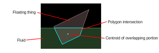
We can simulate this effect in Box2D by finding the displaced fluid mass, and applying a force equal and opposite to the gravity that would have acted on that mass. The displaced mass will be the area of fluid displaced, multiplied by its density. So the main task is finding the area of overlap between the fluid and the floating object.
We can use sensor fixtures to represent water, and calculate the overlapping portion between the water and other fixtures. A full implementation of this would require an algorithm to calculate the intersection between two polygons, between two circles, and between a polygon and a circle. In this topic we will just look at intersection of two polygons.
Once the overlapping portion between two polygons has been found, we can use its area to calculate the necessary force, and apply that force at the centroid of of the intersecting area. We will also need to apply some drag to stop it bouncing around forever.
 Buoyancy forces need to be calculated and applied every time step. We will use the BeginContact
and EndContact functions of the collision listener to keep track of a list of overlapping fixture
pairs, and every time step we will run through that list and see what forces are necessary. It's
handy to typedef a pair of fixtures like this:
Buoyancy forces need to be calculated and applied every time step. We will use the BeginContact
and EndContact functions of the collision listener to keep track of a list of overlapping fixture
pairs, and every time step we will run through that list and see what forces are necessary. It's
handy to typedef a pair of fixtures like this:
1 | typedef std::pair<b2Fixture*, b2Fixture*> fixturePair; |
1 2 3 4 5 6 7 8 9 10 11 12 13 14 15 16 17 18 19 20 21 22 23 24 | //class member variable std::set<fixturePair> m_fixturePairs; void BeginContact(b2Contact* contact) { b2Fixture* fixtureA = contact->GetFixtureA(); b2Fixture* fixtureB = contact->GetFixtureB(); if ( fixtureA->IsSensor() && fixtureB->GetBody()->GetType() == b2_dynamicBody ) m_fixturePairs.insert( make_pair(fixtureA, fixtureB) ); else if ( fixtureB->IsSensor() && fixtureA->GetBody()->GetType() == b2_dynamicBody ) m_fixturePairs.insert( make_pair(fixtureB, fixtureA) ); } void EndContact(b2Contact* contact) { b2Fixture* fixtureA = contact->GetFixtureA(); b2Fixture* fixtureB = contact->GetFixtureB(); if ( fixtureA->IsSensor() && fixtureB->GetBody()->GetType() == b2_dynamicBody ) m_fixturePairs.erase( make_pair(fixtureA, fixtureB) ); else if ( fixtureB->IsSensor() && fixtureA->GetBody()->GetType() == b2_dynamicBody ) m_fixturePairs.erase( make_pair(fixtureB, fixtureA) ); } |
Of course in a real game you would probably not want to make every sensor a water fixture, so the exact conditions used will depend on your situation. Once we have obtained a list of the currently overlapping and relevant fixture pairs, we can go through that list every time step and do the calculations for their overlapping area.
Intersection of two polygons
Calculating the overlapping portion between two polygons is not a trivial procedure, and although it is a core part of this topic it is not really the main focus. There are many established methods for finding the intersection, and a good place to start is Sutherland-Hodgman polygon clipping, which has source code for a common implementation in many languages. For this topic I took the Javascript version on that page and translated it to C++ to make a function like this:
1 | bool findIntersectionOfFixtures(b2Fixture* fA, b2Fixture* fB, vector<b2Vec2>& outputVertices); |
1 2 3 4 5 6 7 8 9 10 11 12 13 14 15 16 17 18 19 20 21 22 23 24 25 26 27 28 29 30 31 32 33 34 35 36 37 38 39 40 41 42 43 44 45 46 47 48 49 50 51 52 53 54 55 56 57 58 59 60 61 62 | bool inside(b2Vec2 cp1, b2Vec2 cp2, b2Vec2 p) { return (cp2.x-cp1.x)*(p.y-cp1.y) > (cp2.y-cp1.y)*(p.x-cp1.x); } b2Vec2 intersection(b2Vec2 cp1, b2Vec2 cp2, b2Vec2 s, b2Vec2 e) { b2Vec2 dc( cp1.x - cp2.x, cp1.y - cp2.y ); b2Vec2 dp( s.x - e.x, s.y - e.y ); float n1 = cp1.x * cp2.y - cp1.y * cp2.x; float n2 = s.x * e.y - s.y * e.x; float n3 = 1.0 / (dc.x * dp.y - dc.y * dp.x); return b2Vec2( (n1*dp.x - n2*dc.x) * n3, (n1*dp.y - n2*dc.y) * n3); } //http://rosettacode.org/wiki/Sutherland-Hodgman_polygon_clipping#JavaScript //Note that this only works when fB is a convex polygon, but we know all //fixtures in Box2D are convex, so that will not be a problem bool findIntersectionOfFixtures(b2Fixture* fA, b2Fixture* fB, vector<b2Vec2>& outputVertices) { //currently this only handles polygon vs polygon if ( fA->GetShape()->GetType() != b2Shape::e_polygon || fB->GetShape()->GetType() != b2Shape::e_polygon ) return false; b2PolygonShape* polyA = (b2PolygonShape*)fA->GetShape(); b2PolygonShape* polyB = (b2PolygonShape*)fB->GetShape(); //fill subject polygon from fixtureA polygon for (int i = 0; i < polyA->GetVertexCount(); i++) outputVertices.push_back( fA->GetBody()->GetWorldPoint( polyA->GetVertex(i) ) ); //fill clip polygon from fixtureB polygon vector<b2Vec2> clipPolygon; for (int i = 0; i < polyB->GetVertexCount(); i++) clipPolygon.push_back( fB->GetBody()->GetWorldPoint( polyB->GetVertex(i) ) ); b2Vec2 cp1 = clipPolygon[clipPolygon.size()-1]; for (int j = 0; j < clipPolygon.size(); j++) { b2Vec2 cp2 = clipPolygon[j]; if ( outputVertices.empty() ) return false; vector<b2Vec2> inputList = outputVertices; outputVertices.clear(); b2Vec2 s = inputList[inputList.size() - 1]; //last on the input list for (int i = 0; i < inputList.size(); i++) { b2Vec2 e = inputList[i]; if (inside(cp1, cp2, e)) { if (!inside(cp1, cp2, s)) { outputVertices.push_back( intersection(cp1, cp2, s, e) ); } outputVertices.push_back(e); } else if (inside(cp1, cp2, s)) { outputVertices.push_back( intersection(cp1, cp2, s, e) ); } s = e; } cp1 = cp2; } return !outputVertices.empty(); } |
Area and centroid of a polygon
Likewise, calculating the area and centroid of a polygon is not the focus of this topic. Box2D includes a handy function for computing a polygon centroid, which also happens to calculate the area, so we can re-use that with a couple of tiny modifications. The function signature I ended up with is:
1 | b2Vec2 ComputeCentroid(vector<b2Vec2> vs, float& area); |
1 2 3 4 5 6 7 8 9 10 11 12 13 14 15 16 17 18 19 20 21 22 23 24 25 26 27 28 29 30 31 32 33 34 35 36 37 38 39 40 41 42 | //Taken from b2PolygonShape.cpp b2Vec2 ComputeCentroid(vector<b2Vec2> vs, float& area) { int count = (int)vs.size(); b2Assert(count >= 3); b2Vec2 c; c.Set(0.0f, 0.0f); area = 0.0f; // pRef is the reference point for forming triangles. // Its location doesnt change the result (except for rounding error). b2Vec2 pRef(0.0f, 0.0f); const float32 inv3 = 1.0f / 3.0f; for (int32 i = 0; i < count; ++i) { // Triangle vertices. b2Vec2 p1 = pRef; b2Vec2 p2 = vs[i]; b2Vec2 p3 = i + 1 < count ? vs[i+1] : vs[0]; b2Vec2 e1 = p2 - p1; b2Vec2 e2 = p3 - p1; float32 D = b2Cross(e1, e2); float32 triangleArea = 0.5f * D; area += triangleArea; // Area weighted centroid c += triangleArea * inv3 * (p1 + p2 + p3); } // Centroid if (area > b2_epsilon) c *= 1.0f / area; else area = 0; return c; } |
Updating each time step
Once we have the groundwork ready for processing the fixture pairs, we can set up a loop which goes through them every time step:
1 2 3 4 5 6 7 8 9 10 11 12 13 14 15 16 17 18 19 20 21 22 23 | //inside Step(), loop through all currently overlapping fixture pairs set<fixturePair>::iterator it = m_fixturePairs.begin(); set<fixturePair>::iterator end = m_fixturePairs.end(); while (it != end) { //fixtureA is the fluid b2Fixture* fixtureA = it->first; b2Fixture* fixtureB = it->second; float density = fixtureA->GetDensity(); vector<b2Vec2> intersectionPoints; if ( findIntersectionOfFixtures(fixtureA, fixtureB, intersectionPoints) ) { //find centroid float area = 0; b2Vec2 centroid = ComputeCentroid( intersectionPoints, area); //apply buoyancy stuff here... } ++it; } |
Applying buoyancy force
Once we have the overlapping area and centroid for a polygon pair, applying the buoyancy force is dead simple. Multiplying the overlapping area by the density of the fluid gives us the displaced mass, which we can then multiply by gravity to get the force:
1 2 3 4 5 6 | b2Vec2 gravity( 0, -10 ); //apply buoyancy force (fixtureA is the fluid) float displacedMass = fixtureA->GetDensity() * area; b2Vec2 buoyancyForce = displacedMass * -gravity; fixtureB->GetBody()->ApplyForce( buoyancyForce, centroid ); |
Applying simple drag
At this stage, floating bodies will be pushed upwards when they overlap the fluid, but with nothing to slow them down they keep getting faster until they actually jump completely out of the fluid, then fall down, and jump back out, and so on forever. What we need is some drag force to slow these bodies down while they are in the fluid.
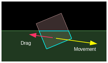 We can create a simple drag by applying a force to the body in the opposite direction to the current
movement, at the centroid position. As we can see from the drag equation,
the magnitude of the drag force should be proportional to the density of the fluid and the square of the velocity.
We can create a simple drag by applying a force to the body in the opposite direction to the current
movement, at the centroid position. As we can see from the drag equation,
the magnitude of the drag force should be proportional to the density of the fluid and the square of the velocity.
1 2 3 4 5 6 7 8 9 | //find relative velocity between object and fluid b2Vec2 velDir = fixtureB->GetBody()->GetLinearVelocityFromWorldPoint( centroid ) - fixtureA->GetBody()->GetLinearVelocityFromWorldPoint( centroid ); float vel = velDir.Normalize(); //apply simple linear drag float dragMag = fixtureA->GetDensity() * vel * vel; b2Vec2 dragForce = dragMag * -velDir; fixtureB->GetBody()->ApplyForce( dragForce, centroid ); |
1 2 3 | //apply simple angular drag float angularDrag = area * -fixtureB->GetBody()->GetAngularVelocity(); fixtureB->GetBody()->ApplyTorque( angularDrag ); |
Better drag
The drag shown above is quite primitive. It makes no difference what shape the floating body is, the drag will always be the same for a given area. We can make a much better calculation for the drag by looking at the individual edges which are actually causing the drag. For instance, we could look at the leading edges of the body as it moves through the fluid, because it is their area which resists the movement.
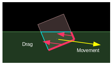 We can use the dot product of the normal of each edge to see whether it is facing the direction of
travel, and how much area it presents as resistance:
We can use the dot product of the normal of each edge to see whether it is facing the direction of
travel, and how much area it presents as resistance:
1 2 3 4 5 6 7 8 9 10 11 12 13 14 15 16 17 18 19 20 21 22 23 24 | //apply drag separately for each polygon edge for (int i = 0; i < intersectionPoints.size(); i++) { //the end points and mid-point of this edge b2Vec2 v0 = intersectionPoints[i]; b2Vec2 v1 = intersectionPoints[(i+1)%intersectionPoints.size()]; b2Vec2 midPoint = 0.5f * (v0+v1); //find relative velocity between object and fluid at edge midpoint b2Vec2 velDir = fixtureB->GetBody()->GetLinearVelocityFromWorldPoint( midPoint ) - fixtureA->GetBody()->GetLinearVelocityFromWorldPoint( midPoint ); float vel = velDir.Normalize(); b2Vec2 edge = v1 - v0; float edgeLength = edge.Normalize(); b2Vec2 normal = b2Cross(-1,edge); //gets perpendicular vector float dragDot = b2Dot(normal, velDir); if ( dragDot < 0 ) continue; //normal points backwards - this is not a leading edge float dragMag = dragDot * edgeLength * density * vel * vel; b2Vec2 dragForce = dragMag * -velDir; fixtureB->GetBody()->ApplyForce( dragForce, midPoint ); } |
Lift
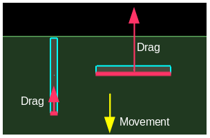
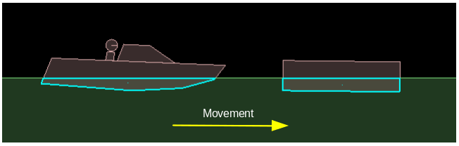
Lift is the force generated perpendicular to the direction of movement. Our simulation is looking reasonably good already with just drag, but without applying any lift force we are missing some nice touches that give extra realism. Consider the situation below - if these two bodies were pushed toward the right, they both present about the same surface area in the direction of travel to resist the movement. So with our current drag force, the resulting effect will be about the same... but that doesn't feel right at all.
 Our natural sense tells us that the body on the left should tend to rise upward as it moves, due to the
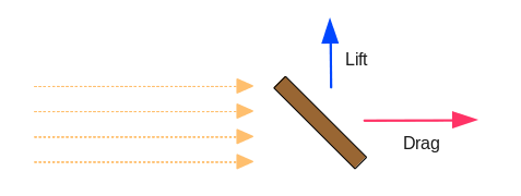
shape of its leading edge. As another example, consider the case below where a plank of wood is held
diagonally in a stream of water, or a sailboat is catching wind in its sail. Drag pushes the plank
downstream, and lift pushes it sideways. (Lift is not necessarily an upwards force, even though the
name kinda sounds like it.)
Our natural sense tells us that the body on the left should tend to rise upward as it moves, due to the
shape of its leading edge. As another example, consider the case below where a plank of wood is held
diagonally in a stream of water, or a sailboat is catching wind in its sail. Drag pushes the plank
downstream, and lift pushes it sideways. (Lift is not necessarily an upwards force, even though the
name kinda sounds like it.)
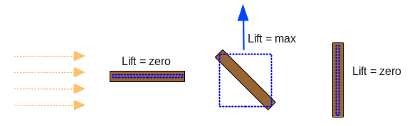
 From searching around the net a while, it seems that what we're dealing with here is known as
flat plate aerodynamics (or hydrodynamics). The lift should be zero when the plank is at right angles
to the stream and highest somewhere in-between, with the maximum force at 45 degrees. You could
consider this to be proportional to the area of the rectangle that the plank is a diagonal of.
From searching around the net a while, it seems that what we're dealing with here is known as
flat plate aerodynamics (or hydrodynamics). The lift should be zero when the plank is at right angles
to the stream and highest somewhere in-between, with the maximum force at 45 degrees. You could
consider this to be proportional to the area of the rectangle that the plank is a diagonal of.
 To put this into a calculation, I have multiplied the dot product that we had earlier (the edge normal and
the direction of movement) with the dot product of the edge direction and the direction of movement. This
effectively becomes cos(angle) * cos(90-angle). One of these is zero at zero degrees, and the other is zero at
ninety degrees, and they are both non-zero in between.
To put this into a calculation, I have multiplied the dot product that we had earlier (the edge normal and
the direction of movement) with the dot product of the edge direction and the direction of movement. This
effectively becomes cos(angle) * cos(90-angle). One of these is zero at zero degrees, and the other is zero at
ninety degrees, and they are both non-zero in between. So for each edge, we add another force in the perpendicular direction. Like drag, lift is also proportional to the density of fluid and the square of the velocity:
1 2 3 4 5 6 | //apply lift float liftDot = b2Dot(edge, velDir); float liftMag = (dragDot * liftDot) * edgeLength * density * vel * vel; b2Vec2 liftDir = b2Cross(1,velDir); //gets perpendicular vector b2Vec2 liftForce = liftMag * liftDir; fixtureB->GetBody()->ApplyForce( liftForce, midPoint ); |
Potential problems
For most simple shapes the approach shown here will work quite well, but when you have a body made from many fixtures the 'leading' edges inside them might cause trouble. Making a body from multiple fixtures is necessary when the desired overall shape is concave, but it can also be necessary for convex surfaces which have more than Box2D's default maximum of 8 vertices. Let's suppose the boat from the example above was made from two individual fixtures.
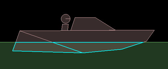 Can you see the problem here? With our current calculations the fixture at the rear of the boat has a
leading edge which will be used to generate drag and lift. The lift will push the boat
downwards as it moves right, and the overall drag will be about twice as strong as it should be. To fix this
problem you would need to use a polygon that describes the overall boat hull rather than using the
individual Box2D fixtures within it.
Can you see the problem here? With our current calculations the fixture at the rear of the boat has a
leading edge which will be used to generate drag and lift. The lift will push the boat
downwards as it moves right, and the overall drag will be about twice as strong as it should be. To fix this
problem you would need to use a polygon that describes the overall boat hull rather than using the
individual Box2D fixtures within it.Source code
Here is the source code for those who would like to try it out for themselves. This is a 'test' for the testbed, based on Box2D v2.3.0.
Testbed test: iforce2d_Buoyancy.zip
Linux 32-bit binary
Linux 64-bit binary
Windows binary
MacOSX binary
YouTube video
RUBE files for the scenes in the video: buoyancyRUBEScenes.zip