

Box2D C++ tutorials - Joints - revolute
Last edited: July 14 2013Chinese version -> 中文
Revolute joints
The revolute joint can be thought of as a hinge, a pin, or an axle. An anchor point is defined on each body, and the bodies will be moved so that these two points are always in the same place, and the relative rotation of the bodies is not restricted.
Revolute joints can be given limits so that the bodies can rotate only to a certain point. They can also be given a motor so that the bodies will try to rotate at a given speed, with a given torque. Common uses for revolute joints include:
- wheels or rollers
- chains or swingbridges (using multiple revolute joints)
- rag-doll joints
- rotating doors, catapults, levers
Creating a revolute joint
A revolute joint is created by first setting the desired properties in a b2RevoluteJointDef, then passing that to CreateJoint to get an instance of a b2RevoluteJoint object. We saw in the joints overview that all joint definitions have some properties in common - the two bodies to be joined, and whether they should collide with each other. So we'll set those first:
1 2 3 4 | b2RevoluteJointDef revoluteJointDef; revoluteJointDef.bodyA = bodyA; revoluteJointDef.bodyB = bodyB; revoluteJointDef.collideConnected = false; |
- localAnchorA - the point in body A around which it will rotate
- localAnchorB - the point in body B around which it will rotate
- referenceAngle - an angle between bodies considered to be zero for the joint angle
- enableLimit - whether the joint limits will be active
- lowerAngle - angle for the lower limit
- upperAngle - angle for the upper limit
- enableMotor - whether the joint motor will be active
- motorSpeed - the target speed of the joint motor
- maxMotorTorque - the maximum allowable torque the motor can use
Local anchors
The local anchor for each body is a point given in local body coordinates to specify what location of the body will be at the center of the rotation. For example, if body A has a 2x2 square polygon fixture, and bodyB has a circular fixture, and you want the circle to rotate about it's center at one corner of the square...
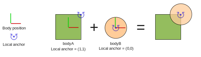 ...you would need local anchors of (1,1) and (0,0) respectively. So the code for this case
would be:
...you would need local anchors of (1,1) and (0,0) respectively. So the code for this case
would be:
1 2 | revoluteJointDef.localAnchorA.Set(1,1); revoluteJointDef.localAnchorB.Set(0,0); |
You can access the anchor points after creating a joint by using GetAnchorA() and GetAnchorB(). Remember the returned locations are in local body coordinates, the same as you set in the joint definition.
Reference angle
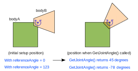
The reference angle allows you to say what the 'joint angle' between the bodies is at the time of creation. This is only important if you want to use GetJointAngle() later in your program to find out how much the joint has rotated, or if you want to use joint limits.
Typically, you will set up the bodies so that the initial rotation is considered to be the zero 'joint angle'. Here is an example of what to expect from GetJointAngle() in the typical case, and the case where a non-zero referenceAngle is given.
 So a typical example is simply as below (the default value is zero anyway so this doesn't
actually do anything).
So a typical example is simply as below (the default value is zero anyway so this doesn't
actually do anything).
1 | revoluteJointDef.referenceAngle = 0; |
 Also, please remember that all angles in Box2D are dealt with in radians, I am just using
degrees here because I find them easier to relate to :p
Also, please remember that all angles in Box2D are dealt with in radians, I am just using
degrees here because I find them easier to relate to :p
Revolute joint limits
With only the properties covered so far the two bodies are free to rotate about their anchor points indefinitely, but revolute joints can also be given limits to restrict their range of rotation. A lower and upper limit can be specified, given in terms of the 'joint angle'.
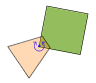
Suppose you want the joint in the example above to be restricted to rotating within 45 degrees of it's initial setup angle.
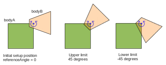 The diagram should explain it fairly well - remember that counter-clockwise rotation of
bodyB means an increase in the joint angle, and angles are in radians:
The diagram should explain it fairly well - remember that counter-clockwise rotation of
bodyB means an increase in the joint angle, and angles are in radians:
1 2 3 | revoluteJointDef.enableLimit = true; revoluteJointDef.lowerAngle = -45 * DEGTORAD; revoluteJointDef.upperAngle = 45 * DEGTORAD; |
1 2 3 4 5 6 7 8 | //alter joint limits void EnableLimit(bool enabled); void SetLimits( float lower, float upper ); //query joint limits bool IsLimitEnabled(); float GetLowerLimit(); float GetUpperLimit(); |
Some things to keep in mind when using joint limits...
-
The enableLimits settings affects both limits, so if you only want one limit you will need to set
the other limit to a very high (for upper limit) or low (for lower limit) value so that it is never
reached. -
A revolute joint's limits can be set so that it rotates more than one full rotation, for example a
lower/upper limit pair of -360,360 would allow two full rotations between limits. -
Setting the limits to the same value is a handy way to 'clamp' the joint to a given angle. This angle
can then be gradually changed to rotate the joint to a desired position while staying impervious to
bumping around by other bodies, and without needing a joint motor. - Very fast rotating joints can go past their limit for a few time steps until they are corrected.
-
Checking if a joint is currently at one of its limits is pretty simple:
bool atLowerLimit = joint->GetJointAngle() <= joint->GetLowerLimit();
bool atUpperLimit = joint->GetJointAngle() >= joint->GetUpperLimit();
Revolute joint motor
The default behaviour of a revolute joint is to rotate without resistance. If you want to control the movement of the bodies you can apply torque or angular impulse to rotate them. You can also set up a joint 'motor' which causes the joint to try to rotate at a specific angular velocity. This is useful if you want to simulate powered rotation such as a car wheel or drawbridge type door.
The angular velocity specified is only a target velocity, meaning there is no guarantee that the joint will actually reach that velocity. By giving the joint motor a maximum allowable torque, you can control how quickly the joint is able to reach the target velocity, or in some cases whether it can reach it at all. The behavior of the torque acting on the joint is the same as in the forces and impulses topic. A typical setting might look like this.
1 2 3 | revoluteJointDef.enableMotor = true; revoluteJointDef.maxMotorTorque = 20; revoluteJointDef.motorSpeed = 360 * DEGTORAD; //1 turn per second counter-clockwise |
1 2 3 4 5 6 7 8 9 | //alter joint motor void EnableMotor(bool enabled); void SetMotorSpeed(float speed); void SetMaxMotorTorque(float torque); //query joint motor bool IsMotorEnabled(); float GetMotorSpeed(); float GetMotorTorque(); |
Some things to keep in mind when using joint motors...
-
With a low max torque setting, the joint can take some time to reach the desired speed. If you make
the connected bodies heavier, you'll need to increase the max torque setting if you want to keep
the same rate of acceleration. -
The motor speed can be set to zero to make the joint try to stay still. With a low max torque setting
this acts like a brake, gradually slowing the joint down. With a high max torque it acts to stop the
joint movement very quickly, and requires a large force to move the joint, kind of like a rusted up wheel. -
The driving wheels of a car or vehicle can be simulated by changing the direction and size of the motor
speed, usually setting the target speed to zero when the car is stopped.
Revolute joint example
Okay, let's make some revolute joints in the testbed to try out these settings and see how they work. First lets make as simple a joint as possible. We'll make one like in the first diagram on this page, using a square and a circle fixture. Since we have already covered many examples I will no longer be showing the full listing for all the code, but in most cases it's probably convenient to start with a basic 'fenced in' type scene as in some of the previous topics to stop things flying off the screen.
Into the scene we will first need to create the box and the circle bodies. It is very common to place the bodies at the position they will be joined in, but for the purpose of demonstration I will make the bodies start a little apart from each other so we can watch how the joint behaves in this situation.
1 2 3 4 5 6 7 8 9 10 11 12 13 14 15 16 17 18 19 20 21 22 23 | //body and fixture defs - the common parts b2BodyDef bodyDef; bodyDef.type = b2_dynamicBody; b2FixtureDef fixtureDef; fixtureDef.density = 1; //two shapes b2PolygonShape boxShape; boxShape.SetAsBox(2,2); b2CircleShape circleShape; circleShape.m_radius = 2; //make box a little to the left bodyDef.position.Set(-3, 10); fixtureDef.shape = &boxShape; m_bodyA = m_world->CreateBody( &bodyDef ); m_bodyA->CreateFixture( &fixtureDef ); //and circle a little to the right bodyDef.position.Set( 3, 10); fixtureDef.shape = &circleShape; m_bodyB = m_world->CreateBody( &bodyDef ); m_bodyB->CreateFixture( &fixtureDef ); |
1 2 3 4 5 6 7 | b2RevoluteJointDef revoluteJointDef; revoluteJointDef.bodyA = m_bodyA; revoluteJointDef.bodyB = m_bodyB; revoluteJointDef.collideConnected = false; revoluteJointDef.localAnchorA.Set(2,2);//the top right corner of the box revoluteJointDef.localAnchorB.Set(0,0);//center of the circle m_joint = (b2RevoluteJoint*)m_world->CreateJoint( &revoluteJointDef ); |
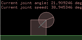
1 2 3 4 | m_debugDraw.DrawString(5, m_textLine, "Current joint angle: %f deg", m_joint->GetJointAngle() * RADTODEG); m_textLine += 15; m_debugDraw.DrawString(5, m_textLine, "Current joint speed: %f deg/s", m_joint->GetJointSpeed() * RADTODEG); m_textLine += 15; |
 Remember that since joints cannot create a perfect constraint like
in the real world, in some cases you might find that the joined bodies can stray from their
correct position, as mentioned in the joints overview topic.
Remember that since joints cannot create a perfect constraint like
in the real world, in some cases you might find that the joined bodies can stray from their
correct position, as mentioned in the joints overview topic.Try moving the anchor positions to see how you can place the pivot point in different locations. For example, try these:
1 2 3 4 5 | //place the bodyB anchor at the edge of the circle revoluteJointDef.localAnchorB.Set(-2,0); //place the bodyA anchor outside the fixture revoluteJointDef.localAnchorA.Set(4,4); |
Now lets set some joint limits. Following the example above, we'll make it able to move within the range -45 to 45 degrees.
1 2 3 | revoluteJointDef.enableLimit = true; revoluteJointDef.lowerAngle = -45 * DEGTORAD; revoluteJointDef.upperAngle = 45 * DEGTORAD; |
Next, let's add a joint motor, also as in the example above. It's more interesting to be able to switch the direction of the motor at runtime, so you could also add a class variable to hold the current motor direction, and use the Keyboard() function to switch it as in some of the previous topics.
1 2 3 | revoluteJointDef.enableMotor = true; revoluteJointDef.maxMotorTorque = 5; revoluteJointDef.motorSpeed = 90 * DEGTORAD;//90 degrees per second |
 If you change the max torque setting to a higher value, around 60, you will see that the joint
can accelerate fast enough so that it does actually reach 90 degrees per second before hitting the
other limit. Try disabling the limit so you can see how the motor will keep the joint at
a stable speed. Add another wheel and you have a simple car!
If you change the max torque setting to a higher value, around 60, you will see that the joint
can accelerate fast enough so that it does actually reach 90 degrees per second before hitting the
other limit. Try disabling the limit so you can see how the motor will keep the joint at
a stable speed. Add another wheel and you have a simple car!Simple chain example
Since chains are quite a common use for revolute joints, we'll give that a try too. A chain is just a bunch of bodies joined together, so they are quite simple to make. First we'll try a loose chain flopping around in the world.
It's best to use a loop to make a chain because the contents are repetitive and with a loop we just change one number to get a longer chain. In one iteration of the loop we need to create a new body as a link in the chain, and attach it to the previous link. To start, let's create the bodies we'll need first:
1 2 3 4 5 6 7 8 9 10 11 12 13 14 15 16 17 18 19 20 21 22 23 | //body and fixture defs are common to all chain links b2BodyDef bodyDef; bodyDef.type = b2_dynamicBody; bodyDef.position.Set(5,10); b2FixtureDef fixtureDef; fixtureDef.density = 1; b2PolygonShape polygonShape; polygonShape.SetAsBox(1,0.25); fixtureDef.shape = &polygonShape; //create first link b2Body* link = m_world->CreateBody( &bodyDef ); link->CreateFixture( &fixtureDef ); //use same definitions to create multiple bodies for (int i = 0; i < 10; i++) { b2Body* newLink = m_world->CreateBody( &bodyDef ); newLink->CreateFixture( &fixtureDef ); //...joint creation will go here... link = newLink;//prepare for next iteration } |
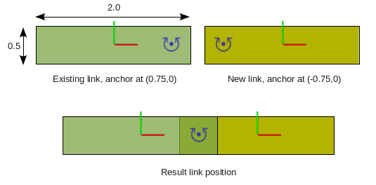
 Now let's think about where the joint anchors will go. Suppose we want them to be at the end of
each chain link, preferably centered rather than on a corner, and inset a little from the
end so that when the link bends it doesn't make any large gaps appear on the outer side.
Now let's think about where the joint anchors will go. Suppose we want them to be at the end of
each chain link, preferably centered rather than on a corner, and inset a little from the
end so that when the link bends it doesn't make any large gaps appear on the outer side.
 The code to do this is pretty easy, it's just a few extra lines:
1 2 3 4 5 6 7 8 9 | //set up the common properties of the joint before entering the loop b2RevoluteJointDef revoluteJointDef; revoluteJointDef.localAnchorA.Set( 0.75,0); revoluteJointDef.localAnchorB.Set(-0.75,0); //inside the loop, only need to change the bodies to be joined revoluteJointDef.bodyA = link; revoluteJointDef.bodyB = newLink; m_world->CreateJoint( &revoluteJointDef ); |
 Right at the beginning of the simulation, the link bodies are still all piled on top of
each other so for a proper game you would want to place the links in a more sensible position
to start with, but the anchor positions will be the same. Notice that the collideConnected property
(default is false) means that each link in the chain will not collide with it's neighboring
links, but it will still collide with all the other links.
Right at the beginning of the simulation, the link bodies are still all piled on top of
each other so for a proper game you would want to place the links in a more sensible position
to start with, but the anchor positions will be the same. Notice that the collideConnected property
(default is false) means that each link in the chain will not collide with it's neighboring
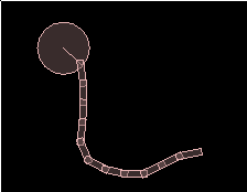
links, but it will still collide with all the other links.Finally, let's try attaching one end of the chain to a grounded body. Make a dynamic body with a circle fixture, and set up a revolute joint to connect it to a static body at it's center. The testbed already has a static body at (0,0) which we can use for this.
1 2 3 4 5 6 7 8 9 10 11 12 13 14 15 16 17 18 19 20 | //body with circle fixture b2CircleShape circleShape; circleShape.m_radius = 2; fixtureDef.shape = &circleShape; b2Body* chainBase = m_world->CreateBody( &bodyDef ); chainBase->CreateFixture( &fixtureDef ); //a revolute joint to connect the circle to the ground revoluteJointDef.bodyA = m_groundBody;//provided by testbed revoluteJointDef.bodyB = chainBase; revoluteJointDef.localAnchorA.Set(4,20);//world coords, because m_groundBody is at (0,0) revoluteJointDef.localAnchorB.Set(0,0);//center of circle m_world->CreateJoint( &revoluteJointDef ); //another revolute joint to connect the chain to the circle revoluteJointDef.bodyA = link;//the last added link of the chain revoluteJointDef.bodyB = chainBase; revoluteJointDef.localAnchorA.Set(0.75,0);//the regular position for chain link joints, as above revoluteJointDef.localAnchorB.Set(1.75,0);//a little in from the edge of the circle m_world->CreateJoint( &revoluteJointDef ); |