


Box2D C++ tutorials - Joints - overview
Last edited: July 14 2013Chinese version -> 中文
Joints
Box2D has a number of 'joints' that can be used to connect two bodies together. These joints can be used to simulate interaction between objects to form hinges, pistons, ropes, wheels, pulleys, vehicles, chains, etc. Learning to use joints effectively helps to create a more engaging and interesting scene.
Lets take a quick look at the available joints, then go over their characteristics, then finally we'll make an example using a few of the most commonly used ones. Here are the joints in Box2D v2.1.2:
- Revolute - a hinge or pin, where the bodies rotate about a common point
- Distance - a point on each body will be kept at a fixed distance apart
- Prismatic - the relative rotation of the two bodies is fixed, and they can slide along an axis
- Line - a combination of revolute and prismatic joints, useful for modelling vehicle suspension
- Weld - holds the bodies at the same orientation
- Pulley - a point on each body will be kept within a certain distance from a point in the world,
where the sum of these two distances is fixed, kinda... (sheesh... there is no succinct way to describe this) - Friction - reduces the relative motion between the two bodies
- Gear - controls two other joints (revolute or prismatic) so that the movement of one affects the other
- Mouse - pulls a point on one body to a location in the world
Joints added after v2.1.2:
In the source code, the actual joint classes are named like b2RevoluteJoint, b2DistanceJoint, etc.
- Wheel - the line joint, renamed
- Rope - a point on each body will be constrained to a maximum distance apart
Creating a joint
Joints are created in a similar way to bodies and fixtures, in that you setup a 'definition' which is then used to create the joint instance itself. The Box2D world manages the actual construction of the joint instance, and when you are done with it you tell the world to destroy it. This process is nothing new for us by now, but just to recap here is how the typical creation of a joint goes (the xxx will be replaced with one of the joint names above):
1 2 3 4 5 6 | //set up the definition for a xxx joint b2xxxJointDef jointDef; jointDef.xxx = ...; //create the joint b2xxxJoint* joint = (b2xxxJoint*)world->CreateJoint( &jointDef ); |
Joints on the other hand each have quite different behavior, in fact so much so that they are implemented as a separate classes, like b2RevoluteJoint, b2DistanceJoint etc. The class b2Joint is the parent of all the classes mentioned above, but it is an abstract class which is never used directly. So when creating joints, although the function CreateJoint does return a b2Joint* type as expected, this is really a pointer to an instance of one of the classes above.
That's why the returned value from CreateJoint has been cast to a b2xxxJoint* in the code above. Of course if you don't need to keep a reference to the joint, you can just call CreateJoint without even storing the returned value at all.
Joint definitions - common settings
Although each joint has a different behavior, you might have guessed from the fact that they have a common parent, they have some features in common too. Here are the fields which are common to every joint definition:
- bodyA - one of the bodies joined by this joint (required!)
- bodyB - the other body joined by this joint (required!)
- collideConnected - specifies whether the two connected bodies should collide with each other
The collideConnected setting allows you to say whether the two bodies should still obey the normal collision rules or not. For example if you are making a rag-doll, you'll probably want to let the upper leg and lower leg segments overlap at the knee, so you would set collideConnected to false. If you are making an elevator platform, you'll probably want the platform to collide with the ground, so collideConnected would be true. The default value is false.
The code up to this point is quite simple, here's an example:
1 2 3 | jointDef.bodyA = upperLegBody; jointDef.bodyB = lowerLegBody; jointDef.collideConnected = false; |
Joint definitions - specific settings
After setting the common fields in a joint definition, you'll need to specify the details for the type of joint you are making. This commonly includes an anchor point on each body, limits on the range of movement, and motor settings. These need to be discussed in more detail for each joint since they are used slightly differently, but here is a general overview of what these terms mean.
- anchor points
Typically a point on each body is given as the location around which the bodies must interact. Depending on
the joint type, this point will be the center of rotation, the locations to keep a certain distance apart, etc. - joint limits
Revolute and prismatic joints can be given limits, which places a restriction on how far the bodies can
rotate or slide. - joint motors
Revolute, prismatic and line (wheel) joints can be given motor settings, which means that instead of spinning
or sliding around freely, the joint acts as if it had it's own power source. The motor is given a maximum force or
torque, and this can be used in combination with a target velocity to spin or slide bodies in relation to each other.
If the velocity is zero, the motor acts like a brake because it aims to reduce any motion between the bodies.
Controlling joints and getting feedback
After a joint is created you can alter the parameters for it's behaviour such as changing the motor speed, direction or strength, enabling or disabling the limits. This can be very useful to build a range of interesting scenes and contraptions, for example wheels to drive a car, an elevator which moves up and down, a drawbridge that opens and closes.
You can also get information about what position the joint is at, how fast it is moving etc. This is useful if you want to use the activity of the joint in your game logic. You can also get the force and torque that the joint is applying to the bodies to keep them in the right place, which can be useful if you want to allow the joint to break when it sustains too much force.
Cleaning up
There are two ways a joint can be destroyed. The first is the same way that bodies and fixtures are destroyed:
1 | world->DestroyJoint( myJoint ); |
1 2 3 4 5 6 7 8 9 | //'myJoint' connects body1 and body2 //BAD! world->DestroyBody( body1 ); // myJoint becomes invalid here world->DestroyJoint( myJoint ); // crash //OK world->DestroyJoint( myJoint ); world->DestroyBody( body1 ); |
Trouble with joint positions
Sometimes you might find that a joint has difficulty keeping the two anchor points in the same place. This has to do with the way the bodies are corrected by the joint. The joint calculates the impulse necessary to push the bodies back into the right alignment, and this impulse is applied to each body with the heavier body being given less of the impulse, and the lighter body being given more.
If there are no other restrictions present (eg. where the two bodies are only interacting with each other) this is fine, and the bodies move as expected according to the impulses. However when another constraint is applied, this balancing of the impulse can be upset by the action of other impulses, usually those acting on the lighter of the two bodies. This is typically seen when a light body has two heavier bodies either joined to it or simply pressing against it. In fact, the same problem can be seen with simple collision resolution where a light body is sandwiched between two significantly heavier bodies, so this issue is not solely a problem with joints.
These are the typical cases:
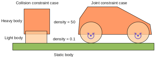 Although in the left case the bodies are not joined, the same type of calculation is going on to
resolve the overlapping fixtures. In each of these situations looking at the forces involved
shows that the light body really is caught between a rock and a hard place.
Although in the left case the bodies are not joined, the same type of calculation is going on to
resolve the overlapping fixtures. In each of these situations looking at the forces involved
shows that the light body really is caught between a rock and a hard place.
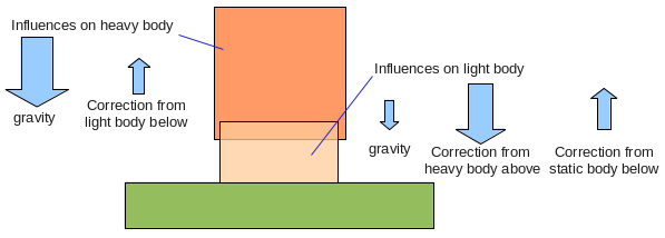 Because it is light,
it is affected most by the correcting impulse, and the heavier body on top is not corrected very
much. The result is that it can take many time steps for the mis-alignment (or overlap in the case
of a collision) to be resolved. Another very common situation where this occurs is when a chain is
made from light segments, and then a heavy body is attached to the end - in that case the light bodies
get 'stretched' rather than squashed as above, but the cause of the problem is the same.
Because it is light,
it is affected most by the correcting impulse, and the heavier body on top is not corrected very
much. The result is that it can take many time steps for the mis-alignment (or overlap in the case
of a collision) to be resolved. Another very common situation where this occurs is when a chain is
made from light segments, and then a heavy body is attached to the end - in that case the light bodies
get 'stretched' rather than squashed as above, but the cause of the problem is the same.The simplest way to overcome this problem is to make bodies that must interact with each other in this way have similar masses. If this seems unreasonable bear in mind that in the real world nothing is perfectly rigid so we never really see this situation occurring, and ideally I guess the object in the middle should be crushed somehow but that's a tricky thing to program. In the case where a heavy object hangs on a chain of light segments, this too in the real world results in either a deformation of the segments or a breakage of the chain altogether (fortunately that's not so tricky to program).
Details on how to use Box2D joints
While joints have some things in common, the differences between them are too great to cover in one topic. Check out the links below for a detailed discussion of specific joints and their usage.